Introduction
Work in the construction industry requires a sound understanding of various types of architectural drawings, their purpose and the differing aspects such drawings show. Architectural drawings are in effect a language: To not be fluent in that language is akin to travelling through a foreign land totally reliant upon an interpreter, never quite sure that what you are being told is fact, fiction, or just that which the interpreter knows will make you feel good….
This text explores the various types of drawings used in construction work, how to read them, and how to draw out the necessary information from those other documents that often accompany them. The first section offers an overview of the various types of drawings, their purpose and the key aspects to be found within them. The second section covers common abbreviations and symbols used in architectural drafting and specifications. The third and forth sections look more closely at the reading of various plans and how to find relevant information within them. The fifth and sixth sections deal with the interpretation of various aspects of the specifications document.
As with any language there are standard systems governing its expression. In the case of architectural drafting these systems are outlined and governed by various Standards and Codes. In Australia, the recommended standards for technical drawings are specified in:
AS1100.101 specifies:
AS1100 Part 301-1985 and its supplement AS1100.301 Supp 1-1986 relate to architectural drawing practice before, during and after construction.
1. Identify types of drawings and their purpose
This section explores the different types of drawings and their purposes, from sketches through to full construction drawings. In addition it covers the differing aspects of construction drawings and what information may be gleamed from them.
Drawing Types
Sketches
Sketches are drawings you will encounter during the design phase of a project. Typically sketch plans illustrate the general layout, form and aesthetics of a residence, building and/or site.
Initial Sketches
Sketch Plans or ‘Roughs’

Pictorial Drawings
The previous examples of sketches show what may loosely described as a basic form of ‘Orthographic’ projection. Orthographic drawings give the familiar ‘plan’ (birds eye or top view), and ‘elevations’ (side views). Orthographic drawings offer the viewer a flat plane depiction of a subject which, whilst useful for describing true lengths and proportions, is a actually not how we ‘see’ an object with our eyes.
In addition, orthographic drawings generally offer only one side, face or ‘plane’ of a structure at a time (i.e.: plane, side elevation, front elevation etc.).
Pictorial drawings attempt to overcome this issue by various means. Isometric and Oblique styles give views of three faces within the one view, with Oblique drawings shortening the lengths of the receding side to give more ‘realistic’ representation of the object.
Perspective drawing is a more advanced form of pictorial drawing that provides very close approximation of how an observer really sees an object. There are various forms of perspective drawing. In its simplest form, the viewer sees things vanish back to one point only. In its most realistic form, things vanish back to three points. Generally drawings are worked to two vanishing points on the ‘horizon’ as shown on the next page.
More information on pictorial and orthographic drawing may be found at:
http://toolboxes.flexiblelearning.net.au/demosites/series9/905/2_draw/draw_t3/htm/draw3_2_1.htm and http://www.khulsey.com/perspective_basics.html
Presentation Drawings
Architects often present artistically ‘rendered’ sketch plans or presentation drawings, to clients. This is in order to assess ideas and concepts expressed in the plans in a more contextually inclusive manner. These drawings are designed to help non technical people understand what the project will look like when complete, and where it will be situated. As shown below, pictorial techniques are used in to advantage.
Construction Drawings
These are the ‘Plans’ as most people would understand them to be. Construction drawings may also be known as ‘working drawings’ ‘architectural drawings’ or ‘Blueprints’. They are a set of detailed technical drawings providing all parties with the requisite information to quote, approve and or construct the building or structure.
Construction drawings use a standard layout of plans, elevations and detail sections defined in AS1100.101 and are generally drawn to scale of 1:100. Specific aspects of a set of such plans will be at larger or smaller scales depending upon the detail required: I.e. Site plans may be at 1:500, whilst details might be as large as 1:5.
Construction Plans:
A set of construction plans will consist of all or some of the following aspects:
Site and Location Plans
The location plan offers generally a larger picture of the surrounding area. Streets, lane ways or other information that ‘locate’ the site of works (such as the specific lot location) within a new suburban development for example, or perhaps that part of a large industrial or educational facility. The Location is usually drawn to a small scale such as 1:1000
The purpose of the site plan is to make clear the location of the structure with regard to boundary lines, the contour or ‘lay’ of the land, and any existing structures, easements and or services immediate to the new works. Scale at 1:200 – 1:500
Floor Plan
A Floor Plan is a horizontal cross section thought a building viewed from above. The purpose of a Floor plan is to detail all horizontal construction dimensions and the general layout of rooms and the like.
There is a lot of informative on floor plans and are usually drawn to a scale of at least 1:100.
Note: Dimensions to all construction drawings in Australia are in millimetres.
Elevations
Elevations show the side views of a building or structure and therefore show heights or vertical distances: hence their name ‘elevations’.

In construction drawings, exterior elevations are drawn, showing the finished appearance. Each elevation is named according to the direction it faces i.e. NORTH, SOUTH, EAST, or WEST elevation. The elevations may show a lot of detail, but seldom much detail offered in the measurements. Only height (elevation) measurements are offered along with ground lines and finished floor and ceiling lines.
Sections
Sections or ‘cross sections’, are drawings used to show detail with greater accuracy by using larger scales. Sectional elevations are cross-sections that cut vertically through a building. The position of sectional elevations are shown on the floor plan by broken lines including arrow heads indicating the direction in which the section is viewed, and an alpha or numeric code by way of identification: I.e. A-A (see previous page – floor plan, and example section A-A below).
The sectional elevation shows such information as:
 depth of footings
Bracing Plans

Details
Detail drawings are enlargements of key areas of a building. In drawing them, the designer gets a clearer picture in their own mind of how a structure might need to be built. In reading them, the builder and client get a clearer picture of areas of work which are perhaps different to normal building practice, or particular to this specific structure.
Examples include:
Schedules
Aside from the bracing schedule described earlier, there are a number of other schedules that may appear on a set of construction drawings. Of these, the most common are the Door and Window Schedule, and the Materials and Finishes Schedule
The Door and Window schedule provides information such as the type, dimension and materials of all windows and doors (internal and external) to the building. This will include the glazing requirements: i.e. double glazed, solar tint, etc. It is usually accompanied by a simplified floor plan showing window and door locations.
Service Details
These drawings are used to show details of services such as electrical wiring, plumbing, heating, ventilation and air-conditioning (HVAC), and plumbing. The scale varies depending upon the complexity of that being depicted. These details are critical to those particular trades involved in the service installation. Generally they form part of the construction drawings or plans discussed previously.
Amendment Drawings
An Amendment Drawing is used to document revisions to original drawings. The amendment drawing may replace the entire drawing, or part of a drawing depending on the scope of the change. The Amendment Drawing may have an Amendment or Revision Block above the title block or a revision number appended to the drawing number. The revision block will detail revision dates, sign off, etc. Revisions are marked on the plan with a triangle pointing to the affected area, with the revision number, and possibly details of the amendments.
Task:
Look at the plan set provided then:
Explore the Australian Standards applicable to various aspects of plans and specifications and determine in what ways, if any, that the plans provided do not adhere to the recommendations in the codes.
Search on the internet, TAFE and or local library, or HIA, MBA or other building associations you may have connections with. Include the BCA in your research if you can access it. If possible obtain copies of the standards.
2. Apply commonly used symbols and abbreviations
The previous section’s purpose was to develop a basic understanding of the common types of drawings and the various aspects of formal construction plans. The purpose of this section is to explore the ‘written language’ of construction plans: that is, to interpret and apply the commonly used symbols, abbreviations and terms used in these drawings. Like any language, by using standardised, common words, symbols, abbreviations and terms, the risk of misunderstandings are reduced (though not eliminated).
Symbols
Symbols are a culturally agreed array of objects, characters, or other concrete figures that abstractly represent ideas, concepts, or desired responses. I.e.: Road signs Traffic lights, road signs, First Aid signs etc..
According to AS1100.301, symbols are used in plans where drawing to scale is impractical. The standard also defines a set of manually drawn feature symbols, but recognises that there are numerous drawing templates and CAD programs with differing symbols. Some site plan symbols are defined in AS1100.401.
There are three main types of symbols
 Some Standard Electrical Symbols
Some Standard Fitting (Plumbing) Symbols
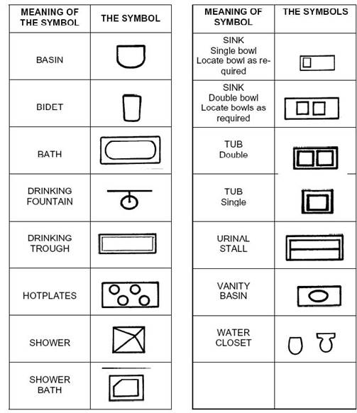
Note: Be aware that whilst some symbols are international, others are nation specific. Some may even look the same but may actually have opposite meanings as you move from one country to another. For example:
Some Standard Material Renderings
Some Standard line types
There are three main types of lines use in drawing to aid plan interpretation: continuos, dashed, and centre lines.
Continuous lines are used to show the main elements of a drawing that may be seen directly in the specific view shown. AS1100 applies different meanings to different thicknesses though this is seldom strictly adhered to.
Dashed lines generally used to draw hidden detail, or detail at levels different to the plan (such as eave lines). They may also be used in overlay plans or footing plans where existing meets the proposed works.
Centre lines are a form of dashed line, the difference being a repeating pattern of short dashes (or dots) with long dashes. Centre lines are used for many things other than marking centres, such as ceiling and floor lines, and section lines as shown in the figure below.

Abbreviations and Terms
Some construction information is presented on drawings as short notes. These convey details such as alternate dimensions, colour, materials, finishes, and draw attention to particular construction or design requirements and the like.
Notes may be annotated arrows, or as cross referenced lists. Abbreviations and standard terms allow notes on drawings to be as concise and clear as possible.
Abbreviations are shortenings of words, usually to save space or effort. The abbreviation is often achieved by using initials to form an acronym, or by omitting parts of the word, AS1100.301 defines a list of standardised abbreviations for use in architectural drawings.
Multiple glossaries of building terms are available on the internet however the student must take care that they are not only Australian, but are not simply adaptations of American or English lists (this same issue can come into play when researching symbols). Some good Australian glossaries may be found at:
http://www.environment.sa.gov.au/heritage/glossary.html#building http://hsc.csu.edu.au/construction/glossary/3246/common_terms.htm
Some sample abbreviations are described below
Acronym |
Term |
Acronym |
Term |
Acronym |
Term |
AL |
Aluminium |
CC |
Concrete Ceiling |
RL |
Reduced Level |
AS |
Australian Standard |
CF |
Concrete Floor |
RSC |
Rolled Steel Channel |
AUX |
Auxiliary |
CTR |
Contour |
RSJ |
Rolled Steel Joist |
B |
Basin |
CORR |
Corrugated |
RWH |
Rain Water Head |
BRR |
Bearer |
D |
Door |
S |
Sink |
BLK |
Block |
DAR |
Dressed All Round |
SD |
Sewer Drain |
BDYL |
Boundary Line |
DP |
Down Pipe |
SEW |
Sewer |
BT |
|
DW |
Dish Washer |
SF |
Strip Footing |
BRKT |
Bracket |
FC |
Fibre Cement |
SHR |
Shower |
BK |
Brick |
FFL |
Finished Floor Line |
SQ |
Square |
BV |
Brick Veneer |
FW |
Floor Waste |
SPR |
Sprinkler |
BWK |
Brick Work |
G |
Gas |
SWBD |
Switchboard |
BLDG |
Building |
GL |
Ground Line |
SWD |
Stormwater Drain |
BL |
Building Line |
HW |
Hot Water Unit |
T |
Truss |
BM |
Bench Mark |
HWD |
Hard Wood |
TC |
Terra Cotta |
CBL |
Cable |
KD |
Kiln Dried |
TM |
Trench Mesh |
CAB |
Cabinet |
MH |
Man Hole |
TR |
Trench |
CAN |
Canopy |
OUT |
Outlet |
TRH |
Trough |
CI |
Cast Iron |
OA |
Over All |
UB |
Universal Beam |
CW |
Cavity Wall |
OH |
Overhead |
U/C |
Under Construction |
CEM |
Cement |
P |
Pier |
U/G |
Underground |
CM |
Cement Mortar |
PBD |
Plaster Board |
UR |
Urinal |
CR |
Cement Render |
PBM |
Permanent Bench Mark |
V |
Vent |
CRS |
Centres |
PCC |
Precast Concrete |
VER |
Version |
CL |
Centre Line |
P/F |
Plan of Subdivision |
VERT |
Vertical |
CHY |
Chimney |
PF |
Portal Frame |
W |
Window |
CCT |
Circuit |
PM |
Permanent Mark |
WBD |
Wallboard |
CD |
Clothes Dryer |
RAD |
Radius |
WC |
Water Closet (Toilet) |
COL |
Column |
RF |
Raft Footing |
WRC |
Western Red Cedar |
C |
Cooker |
RHS |
Rolled Hollow Section |
WPM |
Waterproof Membrane |
3. Locate and identify key features on a site plan
As outlined previously, a site plan is a detailed drawing of a site from an overhead perspective. It identifies the position of the building or buildings on the site. Site plans usually oriented with North to the top of the drawing, with all related drawings displaying a similar orientation (rational to their being viewed as a set of plans). Site plans are drawn to minimum scale 1:200.
Identify the building site from location drawings
The location of a building site will be shown on site plan as distances to boundary lines or neighbouring features such as roadways and adjoining buildings and features. The distance between the front of the building and the front boundary is often referred to as the set back, or front building line. Sometimes a location plan is used when the overall site is large. The location plan will show building site location relative to other sites, vicinity, or entire street.
Task:
Using the plan set provided, identify the following:
Identify true north and building orientation from the site plan.
A compass pointer (North) is always shown on a site plan, and generally with North pointing to the top of the plan. Unless specified otherwise, it may be assumed that ‘True’ North, not ‘Magnetic’ North, is represented. This allows the builder to ‘orientate’ the building appropriately on the site. In addition all boundary lines will have their alignment (in degrees and minutes from North) shown along with their respective lengths.
Identify the key features of the site plan
Some of the key features of a site plan include:
The datum in a site plan is the point which all other site levels refer to. The datum is usually given as a known height above sea level, or a ‘nominal’ height is offered such as 100.00m. In some plans the term Reduced level (RL 100.00) is used. The datum is generally an easily identifiable peg or mark from which the builder may work. This peg or mark being identified on the plan as a TBM (Temporary Bench Mark), BM (Bench Mark), or PM (Permanent Mark): The latter however is generally only to be found outside of the site boundary on a pavement or some council serviceable location.
The Access and Egress features of a site plan show how to get in and out of a site, typically driveway crossovers, paths, right of carriage (use) etc.
Contours lines show the fall of the land. The vertical height difference between on contour and another will depend upon the scale of the drawing, and the level of detail needing to be depicted. Intervals 0.5 to 1.0 metres are common. From the contour lines, the slope can be calculated. Each contour line will
display its level relative to either sea level or the datum.
Slopes or gradients are shown on elevations as a ratio Y: X, where Y is the vertical component and X is the horizontal component of a right angle triangle.
Major geological and topographical features will include trees, rocks, waterways etc Existing dwellings, buildings or other structures on the site will be shown including their dimensions and distances from boundaries and the target building.
Easements confer rights of use of land to someone other than the owner. The easement can also limit development over a nominated area of a site. A typical easement is a service easement allowing service providers’ access to the easement for maintenance purposes. The easement dimensions, distance from boundaries, and identifying codes are documented on the site plan.
Task:
Using the plan set provided, identify the following:
4. Identify and locate key features on drawings
The various aspects of construction drawings discussed previously show specialised and detailed elements of the proposed building and relevant surrounds. This section focuses upon key features of these drawings with the purpose of teasing out the more commonly important detail.
Q. |
Question |
Response |
View |
DWG No. |
1 |
What is the width of the ensuite |
|
|
|
2 |
What is the sectional size of the strutting beams over the living room |
|
|
|
3 |
What is the difference in floor height between dining and living rooms |
|
|
|
4 |
What is the eave width of the entry verandah |
|
|
|
5 |
What is the floor to ceiling height for the master bed room |
|
|
|
6 |
What is the wall height to the living room |
|
|
|
7 |
What type of glass is in W12 |
|
|
|
8 |
What forms of insulation are allowed in the walls |
|
|
|
9 |
What is the approximate pitch of the existing roof |
|
|
|
10 |
How is the bearer tied to the dwarf wall and footing |
|
|
|
11 |
What is the total bracing restraint provided for wind direction 1 |
|
|
|
12 |
What is the minimum the top edge of the strip footing may be below ground level |
|
|
|
13 |
What is the sectional size of the verandah perimeter bearers |
|
|
|
14 |
What is the terrain category for this site |
|
|
|
15 |
What must be done to the ends of the Duragal bearers and joists. |
|
|
|
16 |
Brace B2m offers how many kN of restraint |
|
|
|
17 |
In which room is brace B2m located. |
|
|
|
18 |
What is the ceiling height of the master bedroom entrance |
|
|
|
19 |
What is the sectional size of the rafters to the lounge |
|
|
|
20 |
What material are the lounge rafters to be made from |
|
|
|
21 |
What scale is Detail 2-12 drawn at |
|
|
|
Identify client requested variations
Clients may request variations to the constructions, requiring revised plans. The revisions will be recorded in the plan as a revision number appended to the plan number in the title block, and revision triangles pointing to the affected area on the plan. The affected area may also have a cloud drawn around it to specify the boundaries of the affected area. The revision triangle will be labelled with the revision number and any explanatory notes.
5. Correctly read and interpret specifications
Drawings and Plans present construction information graphically; however there are types of information that are more effectively stated in writing. The specifications hold the written construction information and instructions that cannot be expressed in plans. The specification has legal standing, and forms part of the contract documents along with the working plans. The specifications and construction plans are used during the tendering process.
The specification sections detail:
The specifications sections are grouped by trade, and ordered in the normal sequence of job activity during the construction phase. Builders specialising in project housing often use a standard specification. Standard specifications detail requirements common to buildings of the type, such as:
The specification may also include:
Domestic Construction
In domestic construction the specification is often a schedule in the construction drawings. Aside from a call for adherence to Australian standards nothing else may exist. It is preferable, however, from both client and builder perspectives, to have something ‘tighter’. ‘National’ specifications are available, such as that provided by ‘Natspec’ which cover all aspects at a minimal purchase cost.
Identify and Apply Provisional Sum and Prime Cost Sums
A Provisional Sum (PS) is a sum allowed for in the contract to cover the cost of labour and material for work items when the extent of the work (and materials) could not be determined before construction begins.
The costs of PS items are estimated using either an industry standard construction data reference, such as Cordell’s Housing Building Cost Guide, or by experience. These are then and listed and costed in an addendum to the Specification. Differences between the PS and actual costs are accounted for in the final statement of accounts.
Typical PS items included in a standard addendum are Rock Excavations, Retaining walls, landscaping and pools.
A Prime Cost (PC) is a sum allowed for in the contract, to cover the cost of items which the client or architect has not yet selected. The PC sums may cover the cost of labour and materials, or materials only. The PC items are listed and costed in the specification and in the addenda. Differences between the PC Sum and actual costs are accounted for in the final statement of accounts.
Task:
From the discussion, list 6 items that might be quoted at prime cost only.
Client Variations to Standard Specifications
Frequently the client will seek to have different items to those listed as PC in the standard specifications. In such cases these must be listed in the building schedule (materials and finishes schedule for example) or a ‘Selection Schedule’ (a schedule that contains all specific selections for materials, and items that would otherwise be described as on a Prime Cost basis. Some larger domestic project builders will have a list of ‘PC’ items which are fully costed and from which the client makes their choice prior to the signing of contracts.
Interpret essential elements and apply to estimation, planning and supervisory tasks
Each section of the specification relates to a particular work effort, laying out in detail the builders’ responsibilities, the standards and codes applicable to the work item.
The Introductory section details:
It is important to read the introduction and check that all the specifications and related standards available. If you are not familiar with the standards, read them. Check for, and clear up inconsistencies with the architect or relevant authorities. Make sure that tradesmen are aware of the standards and measurements to be used.
A Statutory Requirements section will itemise:
Builders need to understand how to comply with the relevant Acts and Regulations in the scope and nature of the work. For example, it is critical to ensure all material delivered site is inspected for quality and quantity. When this is not done the builder may become responsible for the missing or defective items. Likewise it is a legislative requirement that a site sign and toilet block are erected prior to starting construction.
The Owners Obligations section lists the owner’s:
A clear and open relationship with the client is essential to good management of construction.
The Plans, Permits and Application Fees section includes:
Although this section may be short, it is critical. Construction cannot proceed without the appropriate permits, payment of fees, and complete plans and drawings being developed. Check plans and drawings are complete and capable of submission for permits and approvals. Make the owner and/or architect aware of any discrepancies and resolve any doubts.
The Site works section covers:
Based upon the site plan, or a more detailed contour plan developed by the builder of a contracted surveyor, an estimation of excavated spoil may need to be developed.
The Foundations and Footings section lists:
It is critical that the builder ensures that contractors have access to the relevant plans and specifications, and that they understand the requirements for this job specifically compared to those processes they might normally use. All work should be monitored for compliance to the specifications.
Other sections of the document
There are numerous sections to a specifications document, and they vary according to the needs of the particular building company, architecturally firm, council, or government department. Typically the document will include headings covering sections which are self explanatory such as:
Identification of Building Codes and Standards
You will find all the building codes and standards listed in the specification against the work item. The main code is the Building Code of Australia, produced by the Australian Building Codes Board (ABCB). The goal of the BCA is to:
“Enable the achievement of nationally consistent, minimum necessary standards of relevant, health, safety, (including structural safety and safety from fire), amenity and sustainability objectives efficiently.”
The BCA has legislative standing in all states and territories of Australia. The BCA refers to certain Australian Standards. Where it does so, those standards also have legal standing. The specification will require that all and / or particular sections of work are to be carried out according to the BCA, particular Australian Standards, or that materials used comply with Australian Standards.
These may include:
As may be seen, there are many standards that may apply. The legal obligation to comply with these standards may be due to their inclusion in the BCA, other codes, or mention in the specification or schedules. The BCA is updated every year, and standards can be subscribed to.
6. Identify non-structural aspects to the specification
Non-structural aspects of a specification generally cover those elements of a building not instrumental in bearing a load or resisting some force (such as uplift, lateral wind forces, or earth pressure on a retaining wall for example). Two common non-structural aspects are:
Identifying the key features of products in the specification
Typically the specification lists these groups of products
Generally the standard specification will allow for the client to have input into most of these items. The choices being based upon aesthetic and service value to which the client will often seek the builders opinion or advice. However, as with the masonry listed above, the standard may specify some constraints upon choice due to energy efficiency requirements (in the case of appliances, plumbing fixtures, window frames or even flooring), and or structural integrity (such as the capacity of glazing to withstand wind forces).
Task:
|
|
|
|
|
|
|
|
|
|
|
|
|
|
|
Source: http://ownerbuildercourse.riverinainstitute.wikispaces.net/file/view/Learner+Guide+BCGBC4012A+MK2a.doc
Web site to visit: http://ownerbuildercourse.riverinainstitute.wikispaces.net
Author of the text: indicated on the source document of the above text
Glenn P. Costin
2010 TAFE NSW Riverina Institute Albury Campus Building & Construction
If you are the author of the text above and you not agree to share your knowledge for teaching, research, scholarship (for fair use as indicated in the United States copyrigh low) please send us an e-mail and we will remove your text quickly. Fair use is a limitation and exception to the exclusive right granted by copyright law to the author of a creative work. In United States copyright law, fair use is a doctrine that permits limited use of copyrighted material without acquiring permission from the rights holders. Examples of fair use include commentary, search engines, criticism, news reporting, research, teaching, library archiving and scholarship. It provides for the legal, unlicensed citation or incorporation of copyrighted material in another author's work under a four-factor balancing test. (source: http://en.wikipedia.org/wiki/Fair_use)
The information of medicine and health contained in the site are of a general nature and purpose which is purely informative and for this reason may not replace in any case, the council of a doctor or a qualified entity legally to the profession.
The following texts are the property of their respective authors and we thank them for giving us the opportunity to share for free to students, teachers and users of the Web their texts will used only for illustrative educational and scientific purposes only.
All the information in our site are given for nonprofit educational purposes
The information of medicine and health contained in the site are of a general nature and purpose which is purely informative and for this reason may not replace in any case, the council of a doctor or a qualified entity legally to the profession.
www.riassuntini.com