AIR COOLING – Examples
Advantages
Simple and less costly to produce.
Lighter engines.
Disadvantages
Difficult to cool all cylinders evenly, especially inline engines.
Difficult to get engine to run at most efficient temperature on ground and at altitude.
Except for small amount of ‘prop-wash’, early systems only effective when aircraft or vehicle is moving forward.
Air cooled engines tend to be noisier than liquid cooled engines.
Not so easy to streamline.
Operation
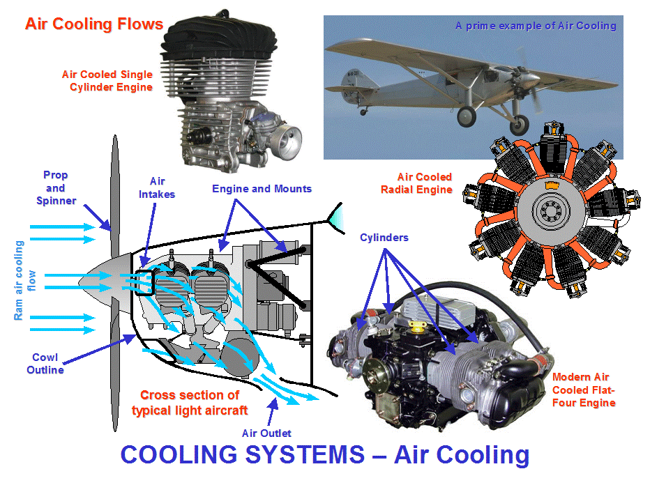
This could not be simple! The single cylinder engine shown below and typical of some motor bike engines, shows the gap between the cooling fins, which allows slipstream air to pass through taking the heat away from the engine.
Examples
The also shown below are a number of different air cooled engines, starting with the Spirit of St Louise, which simply had the radial engine cylinders protruding into the slipstream.
The modern flat four engine is typical of a modern light aircraft type engine.
The powerplant in the Grob Tutor is a Lycoming O-360-A1B6 4-cylinder air-cooled piston engine, of 80 hp; the same engine is used in approximately 50 other aircraft types.
The aircraft cross section bottom left below shows typical cooling airflow through the forward facing intakes, often two, one each side of the spinner directly in line with the engine cylinders. An oultlet at the bottom of the aircraft is provided to allow the cooling flow to escape.
Airflow circulation around engines in different aircraft applications would follow similar principals but differ in detail.

AIR COOLING – Air Flow
Forced Air Cooling
Fan assisted and ducted airflow can over come some of the air cooling disadvantages.
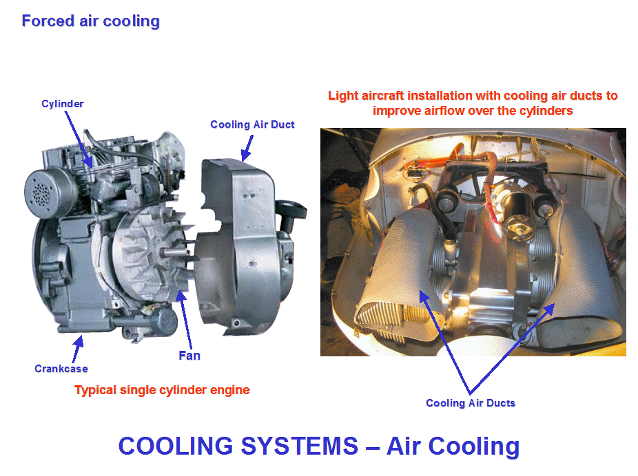
Engines can be fitted with a fan driven by the crankshaft, and a duct to direct the air flow over the cooling fins, as shown by the illustration below. However the downside is that the fan takes some of the available power from the engine.
The engine shown top right below is fan assisted air cooled, this is because it is probably an engine for static (or near static – lawn mower etc) industrial use where a cooling flow would be difficult to achieve.
The photo bottom right below shows a typical light aircraft flat four installation (similar aircraft type to that shown in cross section on the previous page) viewed from above.
Cooling air flow ducts have been fitted to channel the cooling air directly over the cylinder cooling fins, ensuring maximum cooling, and then they curve downwards to take the air to the overboard outlet.
Most modern vehicles have an electrically driven fan instead of a crankshaft driven type. This puts less load on the engine when forced cooling is not required, i.e. the ram air effect when cruising or higher speeds. The fan usually cuts in when in slow moving traffic where forward speed is too low to provide ram air cooling.
Additional fans can be fitted if required, i.e. when towing, the extra work load on the engine means higher running temperatures.

LIQUID COOLING – System
Advantages
The engine temperature can be maintained more evenly over all of the engine.
The operating temperature of the engine can be kept within a narrower range, irrespective of outside air temperature (altitude) or forward speed; this has the further advantage of a longer engine time between overhauls
The more even temperature makes the engine more efficient.
The cooling ‘jacket’ makes the engine quieter.
The engine can be more easily streamlined and thus produce less drag.
Disadvantages
Tend to be heavier.
More complex, more weight, costlier to produce.
As a system needs more maintenance compared to air cooling.
Operation
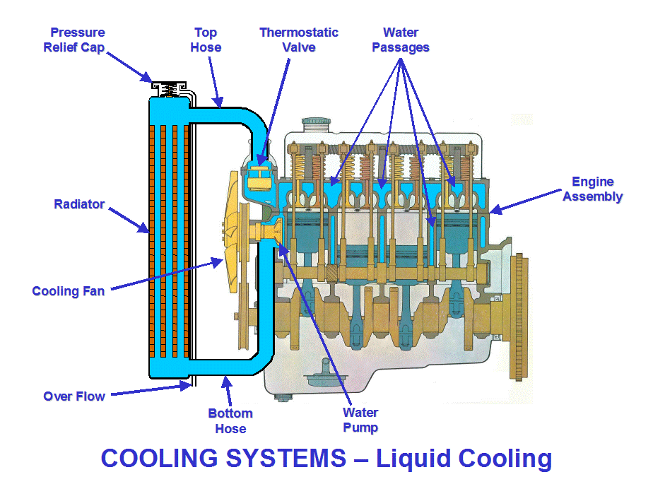
When the engine is running at normal operating temperatures, the engine heated coolant is pumped through the radiator, then recirculated cooled back through the engine block cooling passages.
When the engine is cold the radiator is isolated by the thermostatic valve (see page 10), this ensures the cold coolant is circulated around the engine block only, to ensure the engine reaches normal operating temperature as quickly as possible.
Pressure Relief Valve
The temperature in the engine coolant could easily attain boiling point, and the coolant would boil away.
The boiling point of coolant would get lower with higher altitudes, therefore boiling has to be avoided.
This is achieved by pressurizing the cooling system, at higher pressures the boiling point of fluids will rise.
The pressure relief valve is either on the radiator (older systems) or on the expansion tank (newer systems.
If the system pressure rises above a design value, the excess will bleed off through the relief valve and escape through the overflow tube. Constant loss of fluid with no obvious leaks probably means the relief valve needs replacing.
CAUTION: - NEVER EVER REMOVE THE PRESSURE OR FILLER CAP OFF A HOT ENGINE COOLING SYSTEM.
The hot pressurized coolant will instantly boil off to atmosphere, causing a boiling/steam jet to blast out , and severe scalding could occur.
Wait until the engine temperature has cooled before removing the filler cap. Additionally, cold fluid should not be added to a hot engine, the engine could be damaged as a result.

LIQUID COOLING – Radiator
Description
A radiator is simply a means to transfer heat from one medium to another, as a result, they are more correctly entitled Heat Exchangers.
In the applications described here, unwanted heat from the engine is transferred to the coolant, which in turn is cooled by air passing through the radiator.
Operation
The air and coolant don’t actually mix, they are kept separate from each other. The hot coolant heats up thin metal fins which is cooled by the air passing through; exactly the same principal as the cooling fins on an air cooled engine!
Generally, the coolant flows along horizontal tubes (older system had vertical tubes), above and below which are the corrugated thin metal cooling strip; the tubes and cooling strip are called the ‘Matrix’. On some radiators the cooling strip is also dimpled, this causes a disruption to the airflow and increases the cooling effect.
Heat Exchangers
In this example we have air and coolant as the two mediums, other systems have the following: -
Fuel and Oil – unwanted heat in the engine oil is transferred to the fuel, to prevent fuel icing. Fuel Cooled Oil Coolers (FCOC) or Fuel Oil Heat Exchanger (FOHE).
Air and Oil – unwanted heat in the engine oil is transferred to air, which like the air cooled engine, is then dumped overboard. Air Cooled Oil Cooler (ACOC).
Heat Management Systems
Some modern commercial jet engines have sophisticated heat management systems which can take away unwanted heat from the oil system into the fuel system.
When the fuel could get too hot, some of the fuel is returned to the aircraft tanks which at altitude provide an excellent heat sink without increased drag or loss of energy. The return to tank flow is prohibited at critical stages of the flight, such as take-off and landing.
LIQUID COOLING – Thermostatic Valve
Description
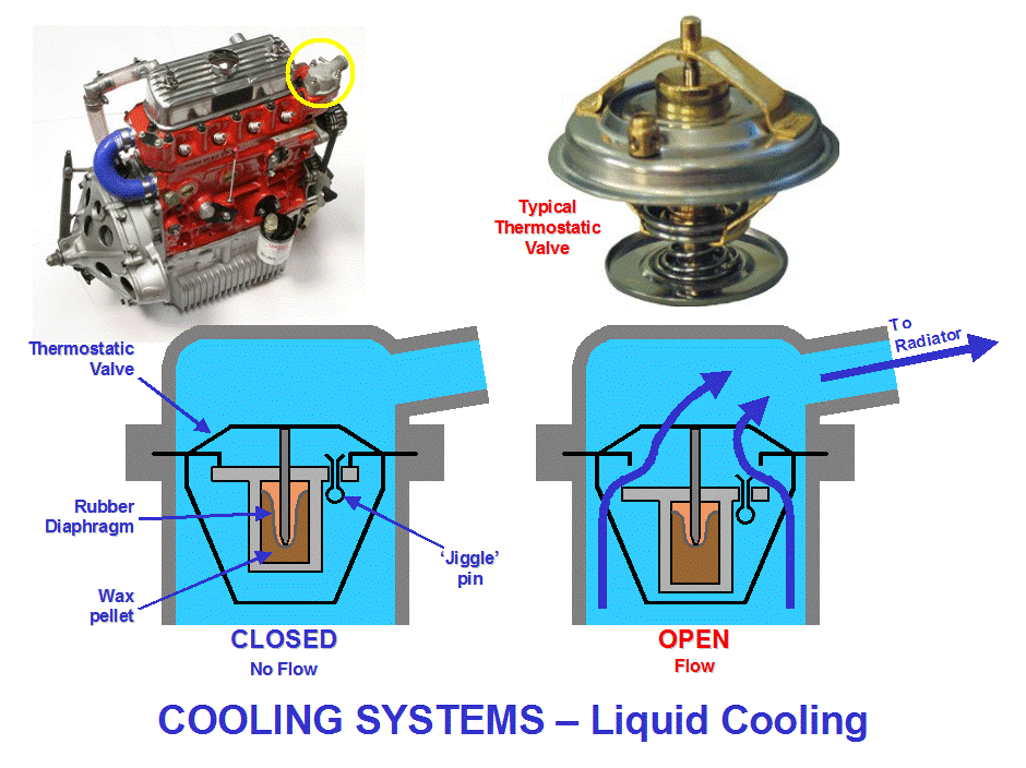
A simple replaceable unit, effectively a heat switch, consisting of a temperature sensitive wax pellet.
Operation
When the engine is cold, the valve is held close by spring force; this forces coolant circulation around the engine block only, i.e. isolating the radiator flow.
(It may sound obvious but when the coolant is cool it does not need the radiator for cooling).
As the coolant heats up, it also heats a wax pellet inside the valve. The wax pellet expands against a rubber diaphragm and pushes the valve open against the spring force.
When the valve opens, coolant is directed to flow through the radiator.
There is a ‘Jiggle-pin’ in the valve plate which allows air to escape, particularly after system replenishment after draining or coolant loss. The pin will also allow a small coolant flow to the radiator so that it starts to heat up before the hot coolant is allowed full flow.
Location
The valve is usually housed in an easy to access bell housing on the engine block, usually where the top hose is connected to the engine.
Maintenance
Failure to operate means the engine will overheat if it is stuck closed, and a slow to heat up engine with little or no heat from the heating system if it is stuck open.
Remove to check if it needs to be cleaned (if it is clogged, flush out the whole system section by section), if it is clean then simply replace – once the wax pellet has failed it cannot be repaired.

LIQUID COOLING – Other Features
Expansion Tank
When radiators had vertical tubes, the header tank was on the top of the radiator.
Most radiators are now horizontal tubes, therefore the ‘tanks’ are at each end. This was done to allow a lower bonnet line for streamlining, but still have the coolant spend the same time in the radiator being cooled; lots of short vertical tubes run the risk of only a few being used.
The expansion tank, as the name suggests, provides space for the heated coolant to expand into. Most systems with an expansion tank have the pressure relieve valve on the tank, and a simple gravity fill priming point on the radiator.
Vehicle Internal Heating
Hot coolant is passed through a heater matrix, which works exactly like a cooling radiator, except the heat is not wasted overboard, but used to heat the vehicle occupants.
The heat control valve regulates the coolant flow, therefore the heat output from the unit.
The air is usually taken in from the bottom of the front windscreen and passes through the matrix into the direction required via the control valves. A multi speed fan can be switched on to increase the air flow.
Source: http://www.299exmouth.com/wp-content/uploads/CHAPTER-7-NOTES.doc
Web site to visit: http://www.299exmouth.com/
Author of the text: not indicated on the source document of the above text
If you are the author of the text above and you not agree to share your knowledge for teaching, research, scholarship (for fair use as indicated in the United States copyrigh low) please send us an e-mail and we will remove your text quickly. Fair use is a limitation and exception to the exclusive right granted by copyright law to the author of a creative work. In United States copyright law, fair use is a doctrine that permits limited use of copyrighted material without acquiring permission from the rights holders. Examples of fair use include commentary, search engines, criticism, news reporting, research, teaching, library archiving and scholarship. It provides for the legal, unlicensed citation or incorporation of copyrighted material in another author's work under a four-factor balancing test. (source: http://en.wikipedia.org/wiki/Fair_use)
The information of medicine and health contained in the site are of a general nature and purpose which is purely informative and for this reason may not replace in any case, the council of a doctor or a qualified entity legally to the profession.
The following texts are the property of their respective authors and we thank them for giving us the opportunity to share for free to students, teachers and users of the Web their texts will used only for illustrative educational and scientific purposes only.
All the information in our site are given for nonprofit educational purposes
The information of medicine and health contained in the site are of a general nature and purpose which is purely informative and for this reason may not replace in any case, the council of a doctor or a qualified entity legally to the profession.
www.riassuntini.com