CHAPTER 5 – FUEL SYSTEM
FUEL SYSTEM – Hydro-Mechanical Systems
System Description
Tanks and Booster Pumps
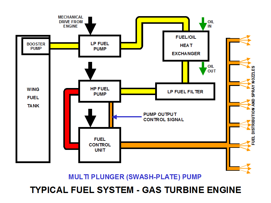
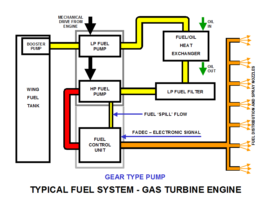
Fuel is pumped from the wing tanks by electrically powered booster pumps. The booster pumps are simply to push the fuel through the extensive aircraft system to the engines.
Low Pressure (LP) Fuel Pump
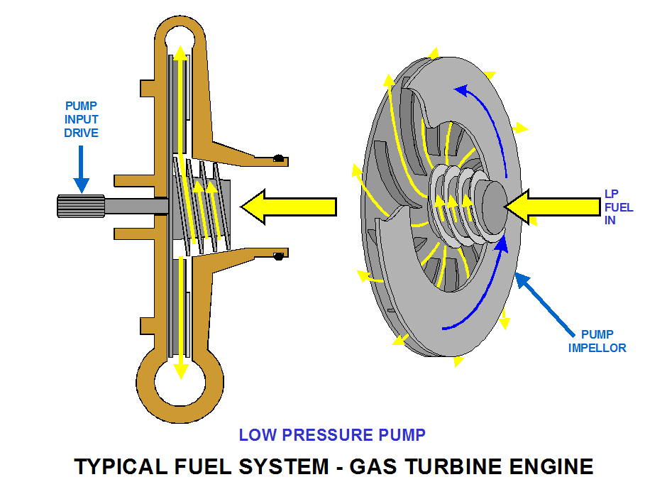
The purpose of the LP fuel pump is to provide a positive pressure to the HP fuel pump. It is a centrifugal type pump driven mechanically by the engine.
Fuel Oil Heat Exchanger
This works like a car radiator, in that heat is transferred from the hot oil to the cold fuel. In older systems, air was used to cool the oil, in modern systems, cold fuel from the wing tanks is used. This has the duel advantage of cooling the engine oil and, preventing fuel blockage due to ice build up in the fuel.
LP Fuel Filter
A simple unit which ensure the fuel is free of damaging contaminants.
High Pressure (HP) Fuel Pump
The purpose of the HP fuel pump is to deliver the fuel at high pressure to the fuel spray nozzles. It is a multi-plunger ‘swash plate’ type pump driven mechanically by the engine. It is a positive displacement pump, which means that flow is proportional to rpm, and if the pump stops turning, fuel will stop flowing.
Fuel Control Unit (FCU)
In this system, the FCU controls the output of the HP fuel pump. The control unit has a mechanical drive from the engine (off the gearbox), so that the control unit knows what speed the engine is running at, and can therefore control the HP pump output as required. HP fuel pump flow control is achieved by a metered fuel pressure signal from the FCU to the HP fuel pump.
Distribution System
This is the system of pipes around the engine which carries the metered fuel pressure to the fuel spray nozzles (FSN’s) in the combustion chamber. The FSN’s have a very small orifice to force the fuel through, this is what achieves the atomization required for efficient combustion.
Some systems have a dual distribution system, to provide good atomization at low rpm’s via a ‘primary’ orifice and the higher fuel flow and atomization at higher rpm’s via a ‘secondary’ orifice.
The FCU splits the fuel flow into primary (higher Pressure) and secondary (lower, but still high, pressure) and each FSN has both the primary and secondary orifices built into it.
FUEL SYSTEM – LP fuel Pump
Low Pressure (LP) Fuel Pump
Purpose
The purpose of the LP fuel pump is to provide a positive pressure to the HP fuel pump.
Type
It is a centrifugal type pump driven mechanically by the engine. It is a non-positive displacement type pump, which means that fuel flow through the pump can be varied at a constant rpm; and, if the pump stops rotating, fuel can continue to flow.
Operation
The LP pump is simple in operation, the rotational force is supplied by the engine via the accessory gearbox.
Like the turbo/super charger, the fuel enters the eye of the rotor, into a ‘scroll’ on modern designs (a coarse slightly conical screw thread not featured in older designs), then the fuel passes into vanes in the rotor. Rotation of the pump forces the fuel to the rim of the rotor by centrifugal force, then on to the pump outlet port.
The flow through the pump is not proportional to the pump rpm, i.e. at high rpm and low fuel flow (when the throttle is closed to slow the engine down) the flow through the LP pump will reduce before rpm reduces. Flow through the pump will always be the same as the combustion flow in the system described here.
FUEL SYSTEM - Fuel/Oil Heat Exchanger and Fuel Filter
Purpose
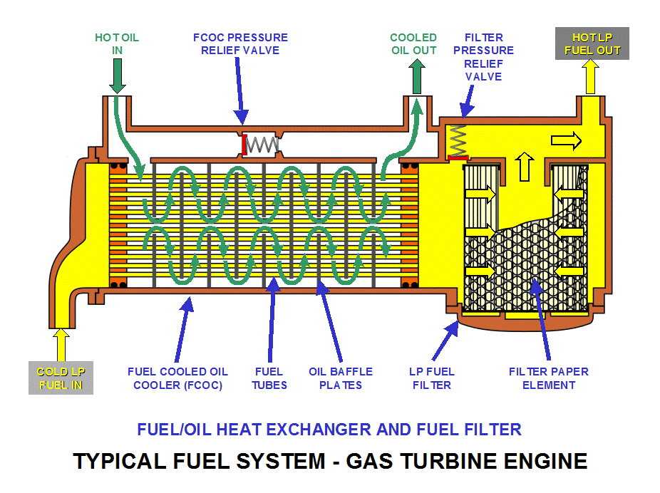
To ensure that the oil is cooled and the fuel is heated, and ensure damaging and/or blockage forming contaminants pass through the fuel control and distribution systems.
Fuel/Oil Heat Exchanger (FOHE)
This unit is also known as the Fuel Cooled Oil Cooler – FCOC.
In earlier systems the oil would be cooled by air (ACOC), but this could leave the problem of fuel icing. So the FOHE has a duel purpose: to cool the oil and prevent fuel icing by the transfer of heat from the hot oil to the cold fuel.
The fuel in the wing tanks is cooled by the very cold temperatures that are found at high altitude. In prolonged altitude cruise flights, the water content of the fuel can become frozen and ice particles can occur which could collect in the filter and cause a blockage in the fuel system preventing sufficient fuel reaching the engine.
In cold ambient temperatures during engine start, the oil can have high viscosity until heated up. To prevent high oil pressures (remember the oil pump starts to pump oil as soon as the engine starts to rotate), a pressure relief valve will automatically open to allow the oil to bypass the cooler element, preventing damage by excessive pressure.
Designers ensure that at the FOHE, the oil is always a higher pressure than the fuel so that, should a leak occur, oil passes into the fuel system and is burnt off (resulting in higher oil consumption) rather that the potentially dangerous situation of volatile fuel leaking into the oil system.
LP Fuel Filter
The filter is a disposable paper element type, and has a filtration rate such that damaging or blockage forming debris/particles are prevented from flowing into the fuel control and distribution system.
The filter has a bypass valve which automatically opens to allow some fuel flow in filter blocked situations, allowing the engine to continue in operation.
Indications
On modern systems, both the FOHE and Filter each have a Differential Pressure switch (differential = the difference between the upstream and downstream pressure of the FOHE and Filter) to pre-warn the flight crew that a problem is occurring before the either bypass valve opens, allowing contingency plans to be put into operation i.e. reducing power and therefore flows, and/or diverting to an airfield for maintenance checks and corrective action.
FUEL SYSTEM – Multi Plunger (Swash-plate) Pump
Description
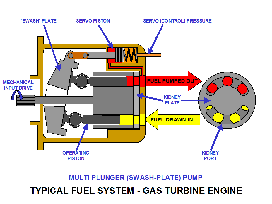
A Positive variable displacement pump, which means that flow is proportional to pump rpm and camplate angle, and if the pump stops rotating, the fuel flow stops as well.
The pump consists of a rotating body which has a number of pistons or plungers, typically in jet engines 7 or 9 depending on the pump size.
Operation
Each plunger works the same as a bicycle pump, when it extends it sucks fuel in; when it is compressed, fuel is pushed out under pressure.
Each piston has a ‘slipper pad’ on a ball joint which is in contact with the camplate, also called a ‘swash-plate’. The camplate does not rotate, but its angle can be changed by servo pressure moving the servo piston.
Therefore, pump flow can be changed at a fixed rpm by changing the camplate angle (a low angle means the pistons have less travel therefore less fuel is drawn in etc), or by changing the pump rpm at a constant camplate angle.
In reality, the pump flow is matched to the combustion flow requirements by changing the camplate angle to provide the correct flow at the speed the pump is driven at by the engine.
The camplate angle is set by HP delivery pressure (HP pump output flow to the fuel flow controller) acting on one side of the servo piston, with a spring and servo pressure (the metered pressure delivered to the engine FSN’s from the fuel flow controller). Changing the HP output pressure and the metered pressure, changes the camplate angle and therefore sets the pump output to match exactly the combustion flow.
FUEL SYSTEM – Multi Plunger Pump Flow Control
Flow Requirements
It is a characteristic of jet engines that controlling the fuel flow is the be all and end all of controlling the engine rpm and therefore power.
In piston engines it is possible to change the mixture without changing rpm, primarily since rpm, particularly in ground vehicles, is set by forward speed, i.e. a direct relationship between engine rpm and road speed through the gearbox.
In jet engines, because there is no direct mechanical link to forward speed, i.e. the engines are free to rotate at whatever speed the fuel flow drives them at (up to governed maximums for safety), there is no possibility of changing the fuel flow without changing the engine rpm/power.**
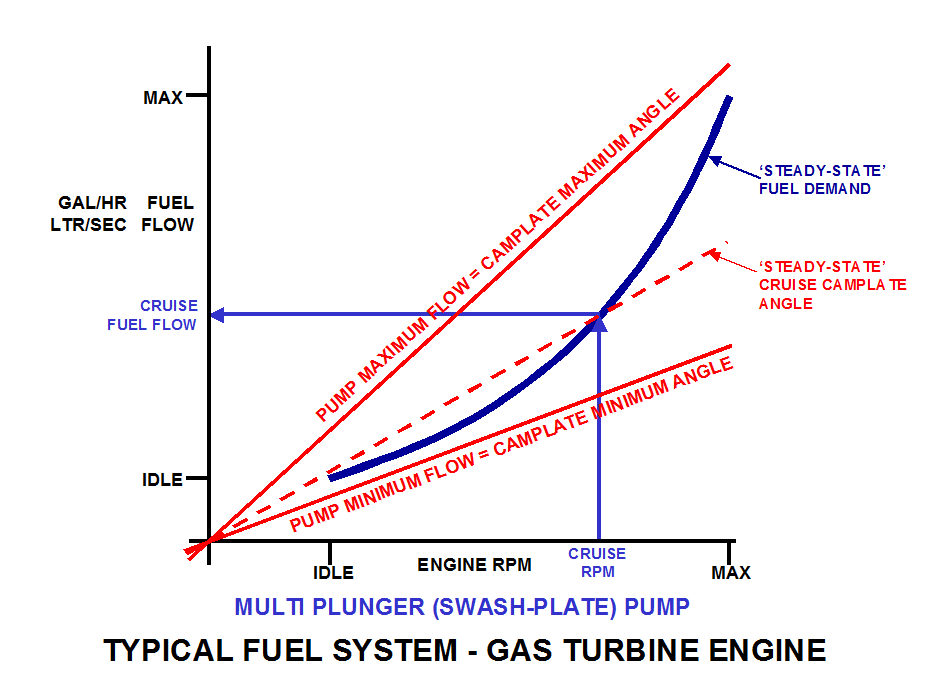
The graph below shows the ‘steady state demand line’. This is the combustion flow, i.e. the amount of fuel required to drive the engine at the constant rpm when the fuel flow was recorded; the curve is an exponential* curve.
The camplate angle has a maximum and minimum angle, limited by fixed mechanical stops built into the pump.
It can be seen from the graph below that at a constant rpm, such as cruise power as shown, the pump could deliver either too much fuel or too little fuel to maintain that rpm (too little fuel/lower camplate angle means the engine speed reduces and vice-versa), simply by changing the camplate angle.
Further Discussion/Observation
Study the graph below, it can be seen that the camplate angle would be approximately the same at idle as it is in cruise, the increase in fuel flow is achieved by running the engine (and therefore the pump) at a higher rpm.
Also, accelerating from idle to cruise means the camplate angle would have to first reduce then increase up to the cruise condition.
Additional Information/Clarification
*Exponential
Where a quantity changes linearly at a constant time interval, i.e. every minute (or any constant time interval, or any rpm increase interval) the quantity doubles (or trebles etc).
For instance (imagine cell growth) if 1 is doubled in one minute to 2, another minute later there is 4, another minute 8, and so on. Therefore, starting at 1, in 10 minutes there would be 1024, 11 minutes 2048 etc..
Plot these quantities at a minute interval (or at any constant time interval) and the curve is an exponential curve.
**Jet Engine Mixture Adjustment
The exception to this is the Dart engine, where fuel flow can be changed by a maximum of 4% from the flight deck whilst the engine is running, for corrections for moisture content in the air i.e. the ‘dew point’. As the engine speed is controlled by the propeller, increasing the fuel flow increases the prop pitch and therefore thrust. This is a power restore function due to thrust loss caused by moisture, rather than a power boost over what would be normal for the conditions.
FUEL SYSTEM – Electronically Controlled Systems
Flow Requirements
The flow requirements of a jet engine controlled electronically are exactly the same as a hydro-mechanical system; imagine a jet engine initially fitted with hydro-mechanical fuel system, then modernized with an electronically controlled fuel system. The fuel flow requirements to drive the engine are exactly the same, only the control method has changed.
System
The system below is almost the same as the previously described system for description/training purposes only; in reality, very few engines have fuel control system changes due to the cost of the change.
The main difference is in the control connection from the fuel controller to the HP pump. Whereas in the hydro-mechanical system previously described, this connection is a control pressure, not a flow. In the electronically controlled system, the connection is now simply a return line for excess fuel.
This is due mainly to the type of pump fitted rather than the control method, i.e. some hydro-mechanical systems may have the gear type pump fitted.
Unlike the multi-plunger type pump, the gear type pump is a positive displacement with a flow proportional to the rpm it is driven at.
This means that the pump delivers more fuel that is required by the engine; this ‘excess’ is called the ‘spill flow’ and is returned to the inlet side of the HP pump.
The amount of spill is determined by the fuel controller via a spill valve. This is controlled via parameters such as engine throttle setting, engine power, air temperature; and limited by maximum rpm limiters, maximum gas temperature limiters by the electronic system.
Pump Assemblies
On modern systems the LP and HP pumps are housed in one unit, therefore taking up only one mounting pad on the accessory gearbox. The mechanical drive passes from the gearbox to the gear type pump and then through to the LP pump.
Fuel Control Unit Mounting
The FCU, or Fuel Metering Unit (FMU) is usually bolted to the pump assembly for convenience. These units no longer have a direct mechanical rpm input signal, this comes into the Electronic Control Unit (ECU), and is used in calculating the position of the FMU throttle valve and spill valve.
FUEL SYSTEM – Gear Type Pump
Description
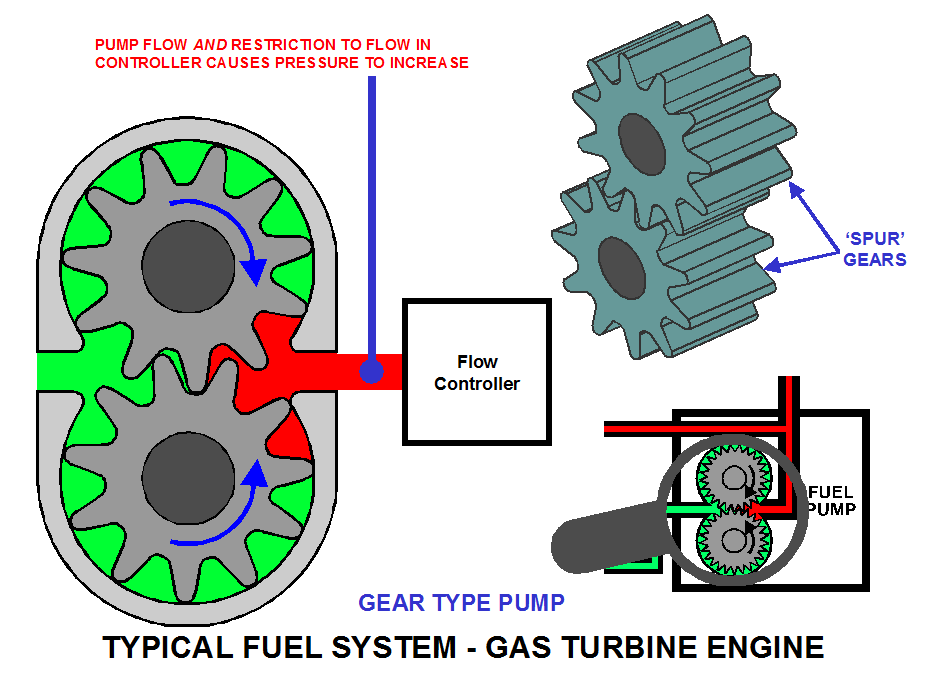
intermeshing straight cut (in this example) spur gears rotating in a close fitting body.
A Positive displacement pump and flow is relative to pump rpm.
Angled gears can reduce pressure pulsations which can occur with straight cut gears.
Operation
One of the gears is the ‘driver’ gear driven by the engine, which in turn drives the ‘driven’ gear via the intermeshing gear teeth.
As the gear rotates, the fluid is carried around the outside of both of the gears between the gear teeth.
A pressure relief valve (not shown below) is usually included to limit absolute pressure (around 450 psi) in the system, to protect against system physical damage, not just to the pump. When the pressure relief valve opens, the excess fluid is simply passed around to the inlet side, or LP - Low Pressure from the HP - High Pressure side of the pump.
Further Discussion
Pressure Values
The pump provides the flow, but if there were no system to pump it through there would be no pressure. Pressure is only achieved because the flow control system works on flow restrictions which causes the pressure to rise. Without the flow controller, the pump would continue to provide a flow but at no pressure.
Spill Flow/Icing
In some systems, the spill fuel flow can be used to help prevent icing in the fuel system and tanks by passing it through another control valve back to the fuel tanks.
When the fuel has passed through the LP and HP pumps and through the FOHE, it is heated to very high temperatures. In certain conditions, this hot fuel can be returned to the tanks to counter the cold temperatures flown in at high altitude, particularly in passenger type aircraft.
At certain flight phases, such as take off, the return to tank flows are prevented. This is to ensure that faults do not starve the engine at a critical stage of the flight.
Pump Design/Choice
Gear type pumps are usually the choice of pump in modern electronic controlled systems, and because of the few, relatively easy and therefore cheaper to produce, moving parts.
FUEL SYSTEM – Gear Type Pump Flow Control
Flow Requirements
The gear type pump is the most favoured pump design as it consists of just a few easy to produce working parts.
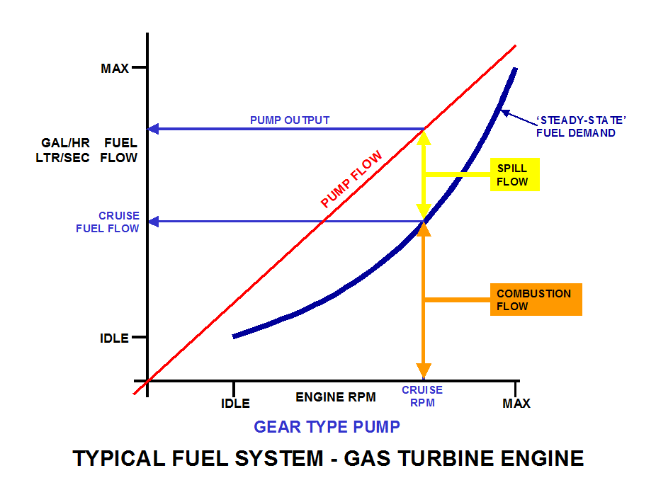
At any given rpm the pump has one output, which is higher that that required for combustion. The pump capacity is set at higher than maximum flow at maximum rpm.
The excess flow, the spill, is returned to the LP side of the fuel system under control of the ECU via the fuel metering and spill valves.
The combustion flow is determined via the throttle position (i.e. power demand), engine and ambient conditions by the ECU.
Acceleration/Deceleration
To accelerate the engine, i.e. increase its speed, the first thing that changes it the fuel flow to the engine. This is achieved by reducing the spill flow which increases the combustion flow. Now the engine is receiving a fuel flow quantity equal to a higher rpm value, so it accelerates.
Deceleration follows the same principal except of course reducing fuel flow to bring rpm down.
To achieve maximum acceleration, the fuel flow is increased by approximately 25%. To decelerate at maximum rate, the fuel flow is reduced by approximately 50%.
A
Source: http://www.299exmouth.com/wp-content/uploads/CHAPTER-5-NOTES.doc
Web site to visit: http://www.299exmouth.com/
Author of the text: not indicated on the source document of the above text
If you are the author of the text above and you not agree to share your knowledge for teaching, research, scholarship (for fair use as indicated in the United States copyrigh low) please send us an e-mail and we will remove your text quickly. Fair use is a limitation and exception to the exclusive right granted by copyright law to the author of a creative work. In United States copyright law, fair use is a doctrine that permits limited use of copyrighted material without acquiring permission from the rights holders. Examples of fair use include commentary, search engines, criticism, news reporting, research, teaching, library archiving and scholarship. It provides for the legal, unlicensed citation or incorporation of copyrighted material in another author's work under a four-factor balancing test. (source: http://en.wikipedia.org/wiki/Fair_use)
The information of medicine and health contained in the site are of a general nature and purpose which is purely informative and for this reason may not replace in any case, the council of a doctor or a qualified entity legally to the profession.
The following texts are the property of their respective authors and we thank them for giving us the opportunity to share for free to students, teachers and users of the Web their texts will used only for illustrative educational and scientific purposes only.
All the information in our site are given for nonprofit educational purposes
The information of medicine and health contained in the site are of a general nature and purpose which is purely informative and for this reason may not replace in any case, the council of a doctor or a qualified entity legally to the profession.
www.riassuntini.com